
April 2021
Few months have passed since the last update from CoFEA Initiative, but it does not mean nothing has been done. Quite contrary! We tested five models, improved the website and connected some dots to establish a simulation workflow based on available open-source software.
Simulation workflow
The following section describes the simulation workflow that we followed when building the models.
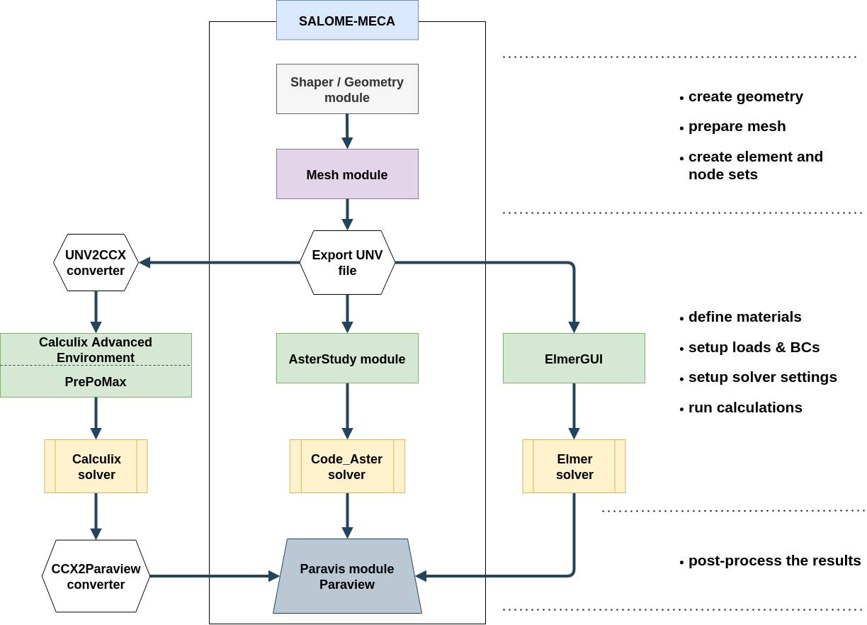
FE simulation workflow based on non-commercial software
Salome vs Salome-Meca
At first, it is worth clarifying the Salome package distribution: Salome and Salome-Meca. Actually, there is only one minor difference between these two. The “ordinary” Salome comes with many useful modules such as Shaper, GEOM, Mesh and ParaVIS (modified Paraview for Salome and Code_Aster), where Salome-Meca has an additional one called Aster_Study (pre-processor for Code_Aster) and contains the pre-compiled Code_Aster solver (this version supports only single-threaded calculations).
Shaper module
Shaper is by now the newest module in the Salome package. It supports parametric modelling with the use of sketches extrusions, revolutions and also boolean operations. If you are familiar with any 3D CAD software you should not have any troubles with making models. The software might not be as robust as SolidWorks, NX and the rest of the crew but hey, it is only one year old and totally for free. Once you make your part in the Shaper module, remember to export it to the GEOM module. Otherwise, you will not be able to create groups for meshing.
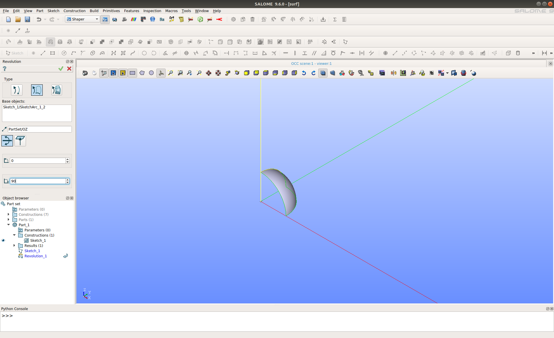
Creation of hemisphere using Shaper
GEOM module
GEOM is an ancestor of previously discussed Shaper. It provides versatile functionalities for the creation, visualisation and modification of geometric CAD models. In our workflow, we use it for group generations from CAD geometry which later can be transformed into groups of elements or nodes.
Mesh module
The goal of this module is simply to create the mesh based on geometrical models created in the GEOM module (or imported from the Shaper). It supports tri/tet and quad/hex meshes and enables the creation of node and element sets.
Hint
The meshes created in Salome are not compatible with CalculiX. While the exported UNV file can be converted into an INP file with the UNV2CCX converter, a different problem related to mesh data may occur. For example, every line in the UNV file is treated as a beam element in the INP file. A similar problem occurs for the 2D geometric features. To avoid having unnecessary element types in the INP file, one needs to delete them first in Salome and then export the UNV file. The procedure to do so is the following:
create the groups on mesh with “Create Groups from Geometry” (the previously created groups in GEOM are used here),
delete undesired entities with “Delete Groups with Contents”.
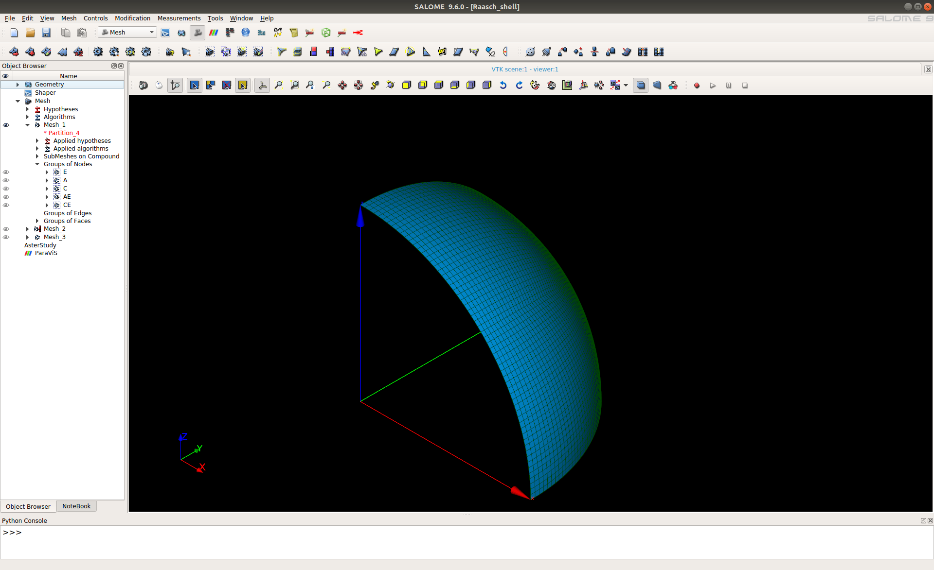
Example of the meshed hemisphere
unv2ccx converter
The use of an unv2ccx converter is pretty straightforward. Just export your mesh to .unv format and then type the command:
unv2ccx mesh_file_name.unv
and voila, your mesh should be converted. Unfortunately, the converter doesn’t support choosing the elements during conversion therefore sometimes element type need to be edited manually in the converted .inp file.
ElmerGrid
ElmerGrid is generally a robust converter which supports the various format of meshes, but it has some drawbacks. The rule of thumb is to avoid using node sets as ElmerGUI doesn’t support it. It is also worth considering every mesh as a standalone case (for example one mesh will convert without any additional flags and the same mesh with quad elements would need a couple of them). Before the conversion process please read the manual and get familiar with these flags: -boundorder, -removelowdim, -removeunused, -bulkorder, -autoclean. They could greatly help you with successful mesh conversion. The .unv mesh is converted with the following command:
ElmerGrid 8 2 mesh_file_name.unv -any_additional_flags
Benchmark conclusions
Five simulation benchmarks modelled in Salome / Code_Aster, Calculix and Elmer gave us some insight into what these codes can do. It is definitely the case that we only scratched the surface, but the simple tests let us also find out how user-friendly a particular software is.
User feeling
If user-friendliness is of interests then we have been quite positively surprised. The latest version of Salome-Meca is definitely one of the greatest environments which are available for free. Rumour has it that the French language has been a bit problematic for user to feel sure that they know what they do. The version available since 2019 has been translated into English quite well (‘well’ in non-native standards). A model can be built in it from scratch, meshed, solved and post-process. For users who know what to look for it will not take long to find the right tool. The others will not find the learning curve very steep as well.
As presented in the simulation workflow chart, we used a mix of Salome-Meca, PrePoMax and Calculix Advanced Environment to build models for Calculix. It is very easy to build a final model in PrePoMax / CAE having already prepared mesh. It is worth saying that it wasn’t that easy a few years ago when these apps did not exist. Of course, they have some glitches, like for example, the latest version of PrePoMax doesn’t allow to assign section in some situations… but at the end of the day they are quite handy and that’s why it is worth checking them.
Elmer was the third code we were testing. The GUI looks very simple, but don’t judge the book by the cover. It actually contains the most important options which allow to set up solver, material, loads etc. Then a user can add some options manually either using keyword editor or directly through the text editor. What is worth saying is that Elmer does not always correctly imported the UNV file exported from Salome (90% of cases were fine). If it could import node sets into the GUI then that would be very useful. Apart from that, it seems to us that the code has very strong capabilities if someone is interested in multiphysics simulation.
Software accuracy
The most important conclusion about the results is that the free software can do a very good job. We achieved the target solutions in all of the tested cases. It can also be seen that in most cases for the same mesh the results are very similar. We think that it might be due to a similar element implementation. For models with such a small DOF number, it was unreasonable to perform a performance comparison, but there are plans to perform such tests in the future. It is also worth noting that we tried to make all the meshes as close as possible to the patterns recommended by NAFEMS.
It has been already proven that a correct solution for the tuning fork benchmark can be obtained using Calculix, Code_Aster and Elmer. With this update, we added result from a test performed using MoFEM code. This Finite Element implementation uses some high-order element shape functions and they allow to achieve quite spectacular results even with coarser mesh. We would like to thank Lukasz Kaczmarczyk for running the eigenvalue analysis for this scenario.
Tuning fork simulation performed in MoFEM
The outcome from the thick plate under pressure case is that it is easy to achieve correct results for a linear model driven by pressure load. The target solution was achieved with both tetrahedral and hexahedral elements.
In Cook’s membrane benchmark, the semi-incompressible material was tested. Two values of Poisson’s value were examined for the linear material model with low Young’s modulus value. It turned out that it might not be feasible to use the linear type of elements to obtain a decent solution. A solution closed to the target value was obtained with quadratic type elements.
With the elliptic membrane under pressure model, the aim was to test the response from a study with the plane stress elements. The benchmark convinced us that it is fairly simple to set up a 2D model and achieve the correct solution.
It can be said that the last model of the hemispherical shell point load model was the most cumbersome to examine. The tests with Code_Aster were quite straightforward, but it took a while to troubleshoot the response in both, Calculix and Elmer. The final conclusion from the tests with Calculix is that the shell implementation does not allow to achieve the correct solution. It seems to us that the symmetry boundary condition has a significant impact on the accuracy of results. The correct solution was achieved with solid elements, which proved our setup to be correct, but usage of those elements was not the point of the study. Setting up symmetry condition for shell elements in Elmer required some tests and the target value was eventually achieved, but for the model with very fine mesh only. The NAFEMS mesh setup does not allow to obtain a decent response, but it should also be noted that the shell implementation in Elmer is still in its’ early phase of development. We would like to also say thank you to all people at the Elmer forum who helped us to debug the model.
Additional notes
It is also worth noting that the work hasn’t been done only on the simulation side. As shown above, we have managed to implement the ipygany extension into our website. This extension let us present interactive plots exported directly from Paraview. Also, we have expanded our Contribution Guide which now describes how to compile the CoFEA docs locally and how to contribute to the initiative.