
Results
Number of simulations with different element types and mesh size have been performed for the hemisphere shell model.
Conclusions
A few conclusions can be derived from the presented study:
It is hard to perform a shell analysis with force loading condition using open-source software and achieve a correct solution. In the current study, only code_aster benchmark mesh was able to obtain a displacement value close to the target of \(u_{x}=0.185 m\).
To obtain precise results with Elmer it is needed to use finer meshes and calculate normal vectors before starting the calculations (mesh.director). For now (27.03.2021) Elmer doesn’t support quadratic shell elements. Please remember that shell solver is under development.
CalculiX was unable to produce correct results with shell elements and symmetry boundary conditions. For more detailed information please read chapter below.
Code_Aster support QUAD_9 instead QUAD_8 elements. Fortunately the solver itself contains a mesh converter to this type of elements.
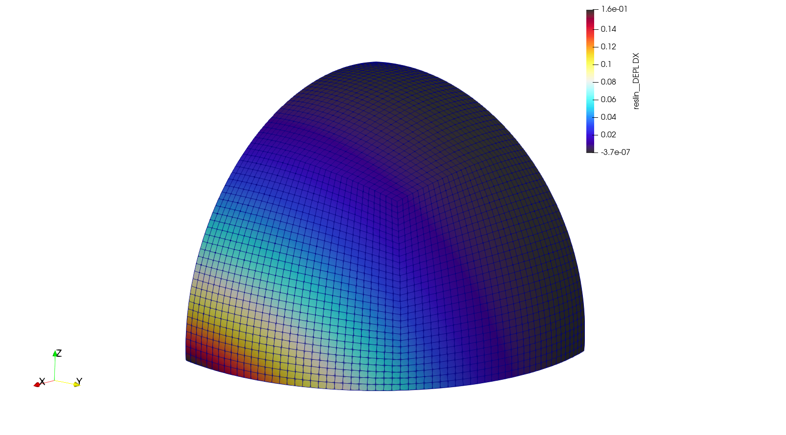
Fig. 21 Results obtained with Code_Aster software and linear hexahedral mesh
Linear quadrilateral mesh
Solver |
Coarse Mesh |
Fine Mesh |
|---|---|---|
CalculiX |
0.000306 m |
0.0000325 m |
Code_Aster |
0.163 m |
0.192 m |
Elmer |
0.009578 m |
0.033597 m |
Quadratic quadrilateral mesh
Solver |
Coarse Mesh |
Fine Mesh |
|---|---|---|
CalculiX |
0.0000431 m |
0.0000792 m |
Code_Aster |
0.147 m |
0.184 m |
Elmer |
no data |
no data |
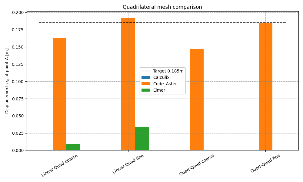
Fig. 22 Graph representing results of the simulation with quadrilateral mesh
Numerous models in CalculiX
In order to obtain correct results with CalculiX 3 models were prepared:
quarter hemisphere model with use of shell S8 elements as described in NAFEMS benchmark,
quarter hemisphere model with use of solid C3D20R elements as described in NAFEMS benchmark,
half sphere model with use of shell S8 elements modeled without symmetry boundary conditions,
Shell element types in CalculiX did not allow to achieve results close to the target value with symmetry boundary conditions. For the hemisphere shell model, the contour of displacement field seems to be similar to the expected one, although the values are still not correct. On the contrary, the solid model with 3 elements per thickness allows to obtain a satisfying result, but it required some time to estimate the response. These comparison proves that the CalculiX model was set up correctly, but it is the shell element type which is the source of non-satisfactory results.
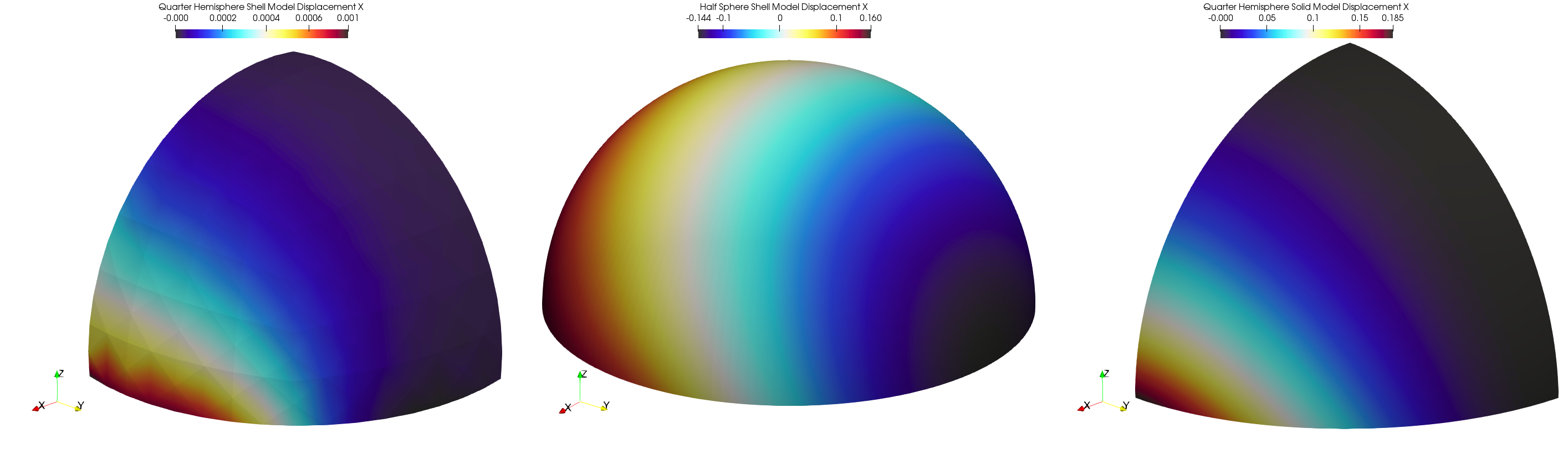
Fig. 23 Graph representing results of different models results in CalculiX from left: S8 shell elements quarter hemisphere model, S8 shell half sphere model, solid C3D20R elements quarter hemisphere model.
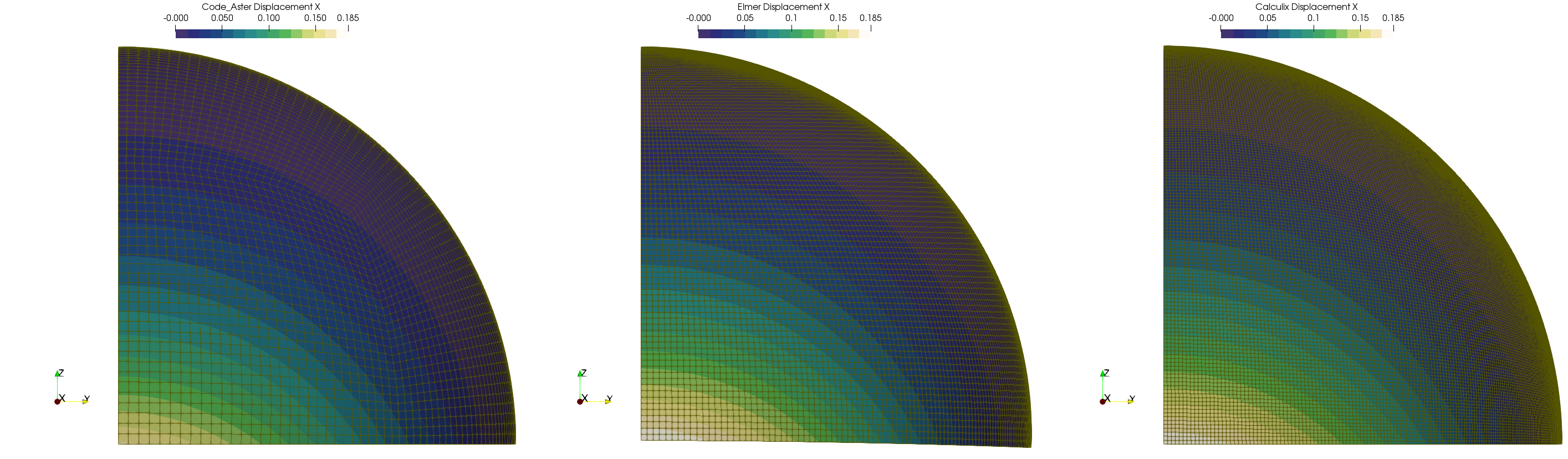
Fig. 24 Results from fine shell mesh in Code_Aster, very fine shell mesh in Elmer and very fine hexahedral mesh in Calculix’