
Results
Conclusions
Calculix
The shell implementation in Calculix did not allow to achieve the target solution. The target solution has been achieved using solid type of elements which proved that the input parameters are correct. A similar conclusion has been derived in the Hemispherical shell point load study.
It is also not possible in Calculix to directly specify a load distributed over an edge. However, one can use a third party software called PrePoMax that allows to define the surface traction load on an edge, which is converted into *CLOAD keyword afterwards. The loading scenario was also approximated with the rigid-body constraint which resulted in the same, incorrect value of displacemt. The last test implies that the source of the error is directly related to the shell element implementation. The provided tests highlight the fact that the shell element in Calculix does not seem to capture the response from the structures with complex shapes.
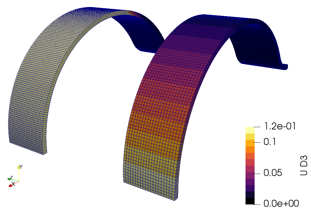
Fig. 26 Difference between the results with shell elements (left) and the solid elements (right)
Code_Aster
Code_Aster allows to run this particular benchmark almost in a frictionless manner. A solution close to the expected value has been achieved even for the linear type of elements. Additionally, the code has a built-in keyword called FORCE_ARETE that allows to specify a load distributed over an edge.
While setting up the solver is straightforward, the post-processing of results with the second-order shell elements might be confusing. Code_Aster solver uses TRIA6_7 or QUAD8_9 element formulation which have an additional node in the middle of element. At the current moment, it is not possible to directly visualise the displacement field in this place. A possible workaround is to run the simulation with the mesh that includes the additional nodes and then project the results onto mesh without them. The section Tested Finite Element codes presents an example of input deck that take advantage of the mentioned workaround.
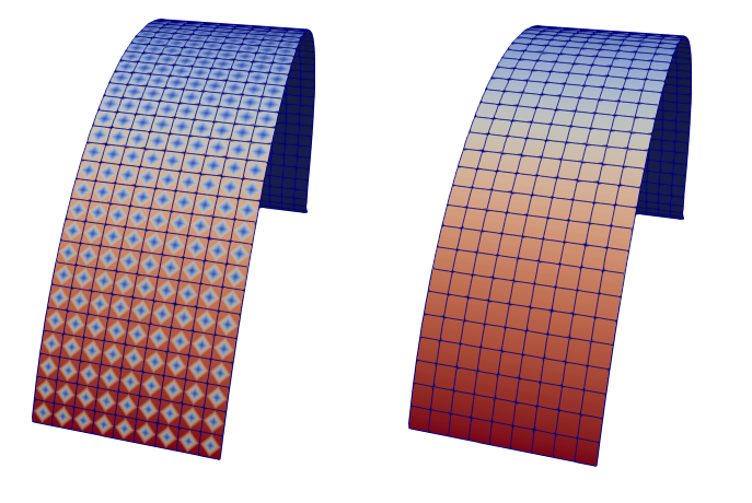
Fig. 27 Inappropriate display of results with the QUAD8_9 elements (left) and the projected results (right)
Elmer
Although the Elmer solver does not support second-order shell elements, it was still possible to achieve a displacement value close to the expected one. The distributed loading conditions have also been easily defined using Resultant Force keyword.
It is worth mentioning that the current shell implementation in Elmer requires a manual definition of shell normals. The definition consists of a file called mesh.director containng node numbers and the normal vectors at the position of a particular node. One can quickly realise that it is rather non-trivial operation to obtain the vectors value for complex shapes. For the case of this particular study, a Python script that aims to be executed in the FreeCAD environment has been prepared. This script loads a BREP representation of the geometry and the Elmer mesh.nodes file, so the precise vector could be computed at any node position. The mentioned script can be found on the CoFEA Github repo.
Mesh convergence study
Linear and Quadratic Triangle mesh
Solver |
Coarse Mesh |
Fine Mesh |
Very Fine Mesh |
|---|---|---|---|
Code_Aster |
0.116 / 0.129 |
0.118 / 0.128 |
0.116 / 0.128 |
Elmer |
0.040 / - |
0.055 / - |
0.084 / - |
Linear and Quadratic Quadrilateral mesh
Solver |
Coarse Mesh |
Fine Mesh |
Very Fine Mesh |
|---|---|---|---|
Code_Aster |
0.112 / 0.130 |
0.118 / 0.128 |
0.116 / 0.127 |
Elmer |
0.0304 / - |
0.052 / - |
0.125 / - |